Why use air valves in water and wastewater applications
Air is present in all water and wastewater pipelines. Therefore, a safe and efficient operation requires continuous removal of air. Air valves contribute to a smooth flow in the pipelines and reduction of maintenance and replacement costs.
All water supply systems consist of pipes that transmit water from its source to its destination. In this process, pockets of trapped air can form in the pipelines. Pockets of air and wastewater gases are difficult to detect and will reduce the overall efficiency of the piping system. The air pockets may also cause water hammer problems, full stoppage of flow, pipe bursts, system noise and pipe corrosion. Air in the pipeline can also cause unstable operation of control valves, meters and equipment. To secure a safe and efficient operation it is therefore critical to continually remove air and wastewater gases from the water system.
Why air appears in pipelines
Dissolved air exists in all fluid transmission systems. The principal sources are:
- Incomplete filling of the line which leaves air pockets at pipeline peaks
- Dissolved air released from the fluid when pressure drops and/or temperature rises
- Air sucked into the system through openings at e.g. joints, breaks/bursts and accessories
If the volume of the air and wastewater gas pocket reaches a certain size, which especially occurs at pipeline peaks where air pockets naturally collect, a restriction of the flow occurs that produces unnecessary headloss risking complete stop of the water flow.
Why vacuum occurs in pipelines
Vacuum can occur in pipes due to lack of air in the system causing severe irreversible issues. Negative pressures left unmanaged have been proven to cause:
- Damages of the pipeline causing suction of contaminants, mud and dirt through faulty connections, cracks in pipes and accessories
- Reduced lifetime of the pipeline due to positive and negative pressures acting on the pipe wall. This can result in fatigue loading which will weaken and eventually cause failure of the pipe wall. This is especially important on ageing pipelines where material degradation is likely
- In extreme cases even pipe collapse
Three issues must coexist for contaminant ingress to take place within water distribution systems:
- The existence of a contaminant source external to the distribution pipe (e.g. contaminated ground water)
- A pathway providing a route into the system (failing pipe joints or leaks)
- A driving force (negative pressure within the pipeline)
One solution to prevent contamination is thus to remove one of the three issues: the driving force. Air valves are the most efficient and cost-effective tool to achieve this and by installing and maintaining a system with air valves, negative pressure is managed and removed from the equation, allowing even an ageing network to remain protected from contamination from the soil.
Vacuum in a pressurized pipe system can thus be caused by inefficient air valves not reacting to hydraulic conditions, air valves having failed due to lack of maintenance, and air valves being absent from the pipeline altogether.
Air valves are often associated with the release of air from the system, and therefore commonly known as air release valves. However, this name is misleading as their function of introducing air into the system to avoid vacuum is equally important.
The function of air valves
Air valves are hydromechanical devices with an internal float mechanism designed to release trapped air and wastewater gases during filling and operation of a piping system.
They also ensure air intake during draining to maintain a positive pressure. This is important as negative pressure causes vacuum that may result in pipe collapse and introduction of contaminants to the system.
Therefore, air valves provide protection from transient pressures and entrapped air in pipelines, which are the main causes of bursting, collapsing, and fracturing of pipelines.
With correct use of air valves, you will achieve:
- Reduced energy consumption and operation costs
- Reduced pressure loss
- Reduced delays when filling the pipe system
- Reduced risk of water hammer
- Reduced failure or inaccuracies in flow metering
- Reduced corrosion
- Reduced risk of contamination
- Reduced risk of pipe burst and collapse
- Reduced costs for replacement
- Reduced depreciation due to increased network lifespan
- Reduced required pump capacity due to lower head loss
Three main types of air valves
There are three types of air valves installed in water systems: automatic air valves, air and vacuum valves and combination air valves.
- Automatic air valves continuously release relatively small volumes of air from a pressurized line. When air bubbles appear in the valve, the float will drop, allowing air to be released. When the water rises again, the float will be lifted, and the valve will close.
- Automatic air valves are also known as small orifice air valves and pressure air valves.
- Air and vacuum valves discharge large volumes of air when filling a pipeline. Air and vacuum valves make it possible to admit large volumes of air when lines are drained or when the pressure suddenly drops below atmospheric pressure. Air and vacuum valves are also known as kinetic air valves, large orifice air valves, vacuum breakers, low pressure air valves, air relief valves and single acting air valves.
- Combination air valves combine the function of automatic air valves and air and vacuum valves. The automatic air release function releases accumulated air from the system while it is under pressure, and the air and vacuum function discharges and admits large volumes of air during the filling or draining of pipelines.
When filling the pipeline, the water flow will force the air out through the air and vacuum orifice. During normal operation, the automatic orifice releases trapped air accumulated in the pipeline, while the air and vacuum orifice remains closed. When emptying the pipeline, the float will drop completely, allowing large volume air intake through the air and vacuum orifice to prevent vacuum damage. Combination air valves are also known as double orifice air valves, double acting air valves and dual orifice air valves.
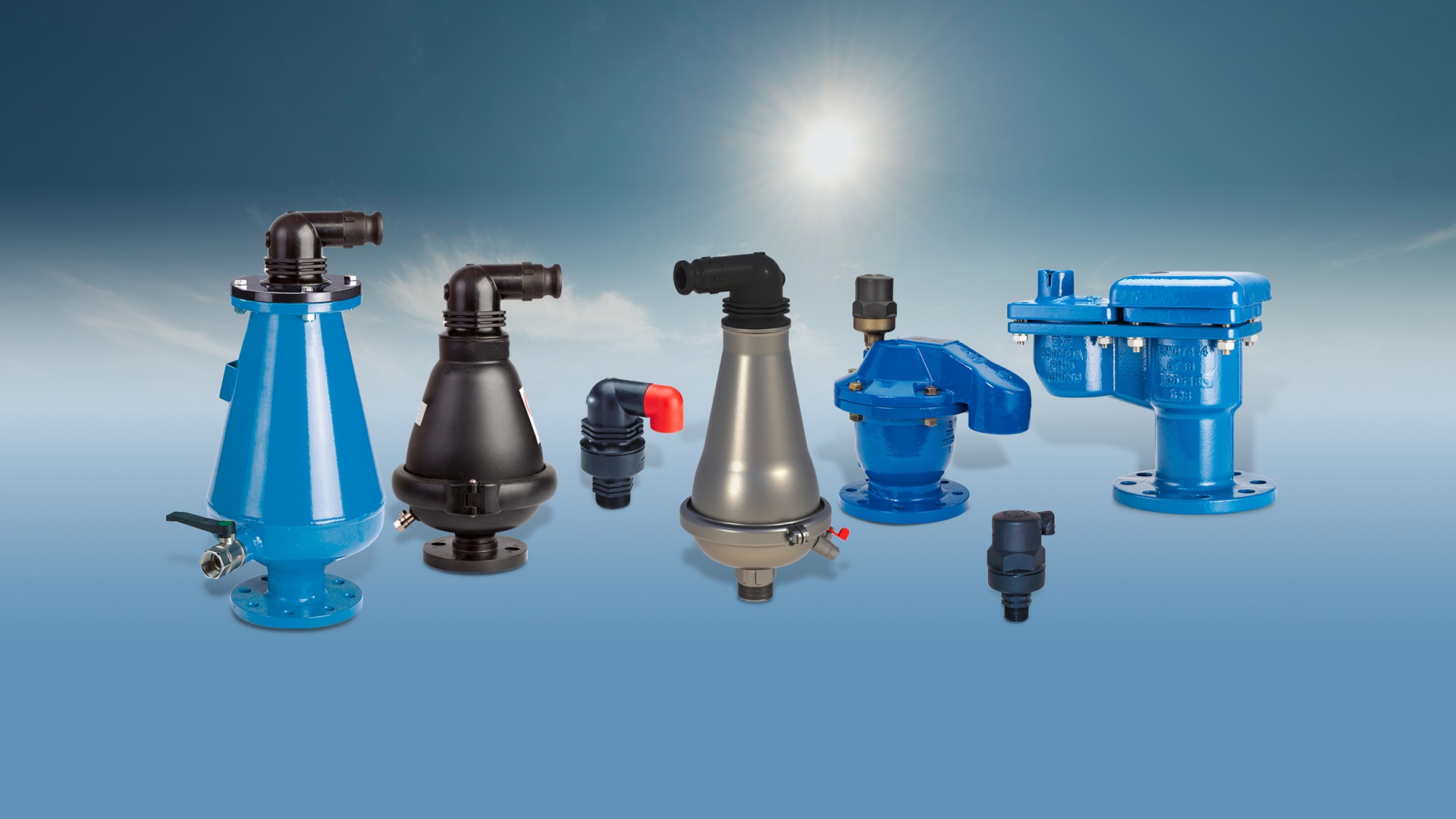
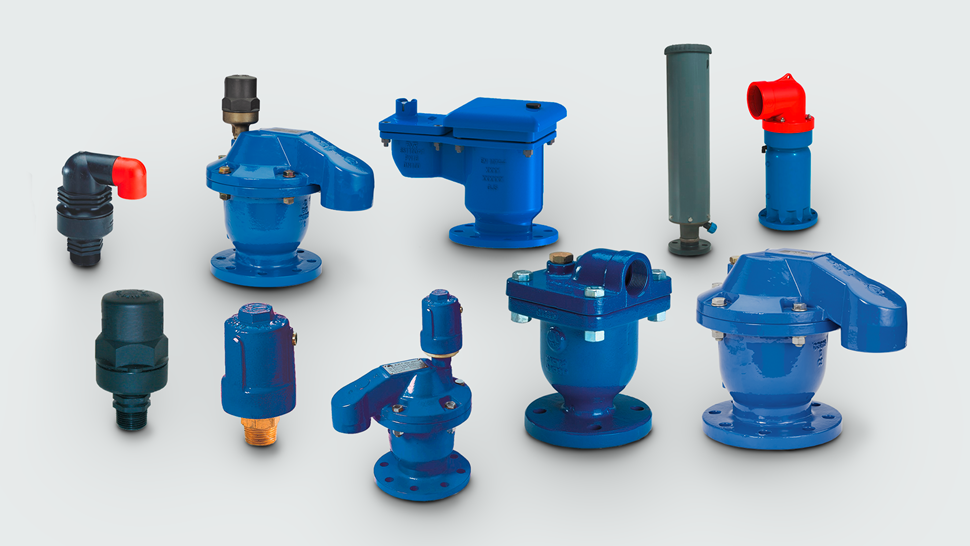
AVK air valves for water supply
Good performance, minimum maintenance and durability are the characteristics of AVK’s wide range of automatic air valves, air and vacuum valves and combination air valves for water supply. The air valves are available in composite materials, which combine strength with extremely light weight.
AVK automatic air valves for water supply
AVK automatic air valves are designed with a very soft and sensitive seal. It enables effective discharge of accumulated air from the system while under pressure. The automatic air valve is light-weight and compact with a 12 mm2 orifice enabling release of air at high flow rates. All operating parts are made of corrosion-resistant materials, and they are available with body of reinforced polyamide (series 701/10) or ductile iron (series 701/20).AVK air and vacuum valves for water supply
AVK air and vacuum valves (series 701/30) feature a dynamic design allowing for high velocity air discharge while preventing premature closure. The special orifice seat design with a combination of bronze and EPDM rubber ensures long-term maintenance-free operation.AVK combination air valves for water supply
Combination air valves combine the function of automatic air valves and air and vacuum valves. AVK offers the following main types of combination air valves for water supply:
- Compact design with rolling seal mechanism, reinforced polyamide (701/40)
- Compact design with rolling seal mechanism, ductile iron (701/46)
- Automatic air valve 701/10 mounted on the air and vacuum valve 701/30 (701/50)
- Automatic air valve 701/20 mounted on the air and vacuum valve 701/30 (701/60)
- Underground air valve unit consisting of an 701/40 air valve in a valve box of PVC/polypropylene (701/84)
- Double-float design, ductile iron (851/41 with ABS float) and (851/45 with SS316 float)
The AVK underground air valve unit (701/84) is designed to save manhole costs. It provides frost protection and is suitable for installation of air valves under important crossings like roads and buildings where manholes would cause dangerous undermining of the ground.
AVK air valves for wastewater treatment
AVK combination air valves for wastewater are designed with a large air gap between liquid and sealing system ensuring a reliable function, even when used with aggressive liquids and liquids containing solid particles.
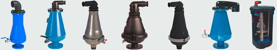
AVK offers the following main types of air valves for wastewater treatment:
- Air and vacuum valve, steel, PN16 (701/33)
- Combination air valve, steel, PN16 (701/70)
- Combination air valve, stainless steel, PN16 (701/96)
- Combination air valve, reinforced polyamide, PN10 (701/75)
- Combination air valve, reinforced polyamide, PN16 (701/95)
- Large combination air valve, steel, PN16 (701/78)
- Underground combination air valve, air valve reinforced polyamide in valve box of polypropylene, PN10 (701/79)
The underground air valve is a competitive solution compared to a typical chamber construction and offers convenient and fast access to maintenance from ground level, even when the system is under pressure. When maintenance is needed, the pressure is released by means of the ball valve, the knife gate shut-off valve is closed by means of the T-key, and the complete valve assembly is taken out for service or maintenance. Alternatively, the system can be backflushed on site.
Features of AVK combination air valves for wastewater treatment
- Large air gap between liquid and sealing ensures reliable function
- Conical shape allows maximum air volume in a reduced valve size
- Funnel-shaped lower body prevents accumulation of deposits
- Low-weight body of steel or reinforced polyamide
- Large automatic orifice releases large volumes of air under pressure
- Spring between upper and lower float prevents unnecessary activation of the automatic function
- Drainage and flushing from external clean water source is possible
- An exhaust tube can be mounted in the threaded opening on the top of the valve
Sizing and location of air valves
Air valves are dimensioned for a specific installation with considerations of flow, location and air valve performance. Thus, the DN of the air valve is not equal to the DN of the pipe, on which it is installed. The size and location of air valves for a specific project are defined by means of advanced calculation programs providing analyses such as fill rate analysis, drainage analysis, burst analysis, water column separation analysis and energy saving analysis.
The primary function of an air valve is to release unwanted air pockets from a pipeline, but it only functions effectively when correctly installed. The proper location of the air valve can improve water flow performance significantly. Therefore, air valves should be installed at those points where the pipeline is most susceptible to vacuum conditions. In general, the optimal installation of an air valve is at the pipeline peak, and the valve must always be installed vertically.
Before installation of an air valve, the location must be considered so that the valve is protected against freezing, pollution and flooding. The air valve should be easily accessible to allow maintenance, operation and inspection.
Recommended placement of air valves
(Source: 3. American Water Works Association, AWWA M11 "Steel Pipe: A Guide for Design & Installation"; 3rd ed., 1989, pp. 98 to 99.)
- High points: combination air valve
- Long horizontal runs: air release or combination valves at 380 meter to 760 meter intervals
- Long descents: combination air valves at 380 meters to 760 meters intervals
- Long ascents: air/vacuum valves at 380 meters to 760 meters intervals
- Decrease in an up slope: air/vacuum valve
- Increase in a down slope: combination air valve
On very long horizontal runs, air release and combination air valves should be used alternately along the pipeline. Note that combination air valves can be used at any location instead of air release or air/vacuum valves to provide added air release capacity on the pipeline.


